Optical metrology · Software development · Image processing
Optical metrology · Software development · Image processing
Welcome
Company
News
Exhibitions
Products
Optics Test Equipment
measuring systems for drawing dies and punches
drawing die and wire measurement
Contact angle measuring systems
Micro scriber, Wafer contact angle, wafer stress measurement
Straightness, Flatness, positioning uncertainty by autocollimator
Measuring microscopes, Image processing
Flatness, Bow, Warp, curvature, glass thickness
Measuring systems for image intensifier tubes (IIT)
Product videos
Software Download
COMEF
ELCOLEVEL
ELCOWIN
RTM
SURFTENS
Teamviewer
Contact
ISO 9001 Certificate
Representatives
privacy policy
Products > Measuring microscopes, Image processing + Micro scriber, Wafer contact angle, wafer stress measurement > Line width measurement
COMEF is an image processing software with special functions for the highly accurate measurement of line width and line distance. Using grey value algorithms, the width and distance of conductor lines or structures on silicon wafers can be measured with subpixel accuracy.
Get in touch >
Download PDF
Description
Download PDF
Description
Increase of accuracy by subpixeling
What are »pixels« and which influence have them on the measuring accuracy?
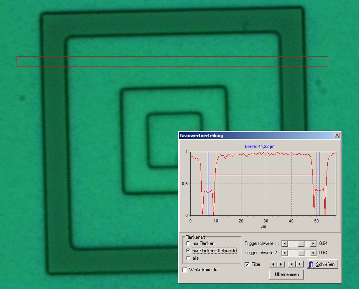
The red rectangle is the measuring field. The measurement takes place, using the greyscale distribution.
Pixels are photo-sensitive elements on the CCD chip. The size of the pixels determines the geometrical resolution of the chip. For this however still the scale of the optics must be considered (also called: magnification ß’).
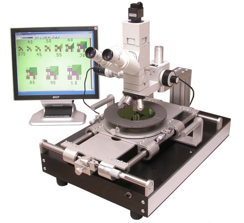
Simple measuring microscope with image processing system for line width measurement
It applies the principle: the optical imaging is reversible. Therefore one can imagine also the CCD chip into the object plane (specimen plane). A micro objective, which images the test specimen with the enlargement 10x into the chip level, images also in principle the chip with the enlargement 1/10 into the test specimen level.
With an original pixel size of 6µm on the chip a pixel in the test specimen level therefore possesses a size of 0,6µm.
Ability all pixels 1:1 on the PC monitor to be represented, can therefore be positioned the mouse cursor in steps by 0,6µm on the picture.
That is the geometrical resolution, with which a measuring point on the monitor can be setted.
The reference to »geometrical« resolution is importantly, because there still other factors (the electronic signal transmission, optical aberrations) the resolution affects.
These influences are however small and with difficulty general to quantify
Generally the following formula applies to the theoretical limit of the detection of an edge position, when manual setting of measuring points on the PC monitor:
ΔXm= P / β´ (1)
with: ΔXm= uncertainty when manual setting of measuring points (=measuring resolution),
P= Pixel distance on the CCD chip, β´= Scale (magnification)
Since resolution is not equal measuring accuracy and contains the formula also some generalizing acceptance, this indication is to be understood as approximate value for the estimation from attainable measuring accuracies to.
For normal measuring applications one estimates the attainable accuracy with approx. 5ΔX. In our regarded case is to be counted thus on a measuring accuracy from approx. 3µm to.
This approximation applies to the standard measuring functions of COMEF.
Increase of the measuring accuracy by Subpixel algorithms
Who was occupied already once with image processing, surely the term »subpixeling« is well-known.
What does one understand by subpixeling?
Subpixeling means, detection of edge position with higher reproductibility than ΔXm.
How does that work?
A condition is that the recognition of the edge position does not take place manually any longer via setting measuring points on the PC monitor.
The edge recognition is made on the basis of grey tone distributions by the regarded screen window. Thus this measuring procedure no more is suitable for all kinds by objects.
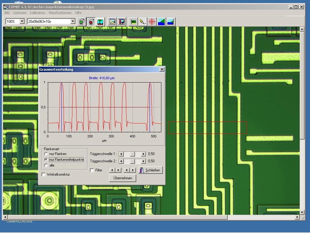
It works however outstanding perfect for all linear expanded objects, thus e.g. for circuit paths on hoppers or structures on wafers and masks in semiconductor technology.
The picture right shows a classical application for the so-called »grey tone processing«. The picture left shows the grey tone distribution in on the right of red drawn in measuring field.
If these procedures application can find, the following formula is valid:
ΔXG= P / (nG * β´) (2)
with: ΔXG= uncertainty for edge detection with grey ton distribution (=measuring resolution), P= Pixel distance on the CCD chip, β´= Scale (magnification), nG=number of grey tones
With usually 256 grey tones in a standard digital image results the theoretical limit for the resolution of the detection of an edge position to: ΔXG= 6µm / (256 * 10) = 0,00234 µm.
That means in pixels: 1/2560 pixels.
In practice this value is not reached naturally (not 256 real grey tones in the image available, influence of environment, optics, signal processing). The actually attainable value depends particularly for this measuring function very on the object contrast. That comes out also from the formula. In practice we assume 100 grey tones in the image. Then the theoretical limit results to a resolution of 6nm. In respect to all possible error sources we can reach in practice an accuracy of edge detection of approximately 100nm = 0.1µm.
All the same whether manual measurement or measurement is by means of grey tone processing, COMEF the ideal tool for the highly exact measurement of digital pictures