Optical metrology · Software development · Image processing
Optical metrology · Software development · Image processing
Welcome
Company
News
Exhibitions
Products
Optics Test Equipment
measuring systems for drawing dies and punches
drawing die and wire measurement
Contact angle measuring systems
Micro scriber, Wafer contact angle, wafer stress measurement
Straightness, Flatness, positioning uncertainty by autocollimator
Measuring microscopes, Image processing
Flatness, Bow, Warp, curvature, glass thickness
Measuring systems for image intensifier tubes (IIT)
Product videos
Software Download
COMEF
ELCOLEVEL
ELCOWIN
RTM
SURFTENS
Teamviewer
Contact
ISO 9001 Certificate
Representatives
privacy policy

Products > Flatness, Bow, Warp, curvature, glass thickness > 1D-glass thickness profile measuring instrument GPM2
Highly accurate automatic measurement of glass thickness distributions
Get in touch >
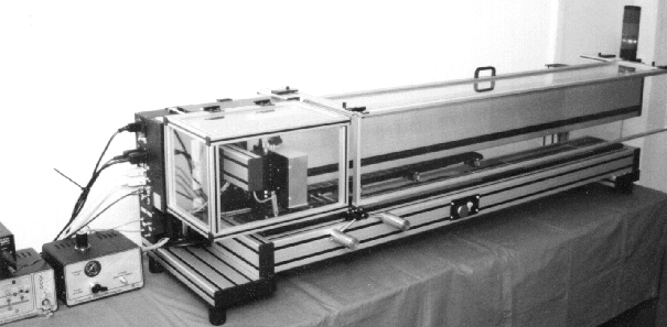
Fig 1: Glass thickness profiler (max. 1200 mm)
Fields of use
The glass thickness profiler GPM has the function to execute a fast and precise determination of the thickness profile of flat glass samples or another transparent material with a thickness range from 30µm to 700µm (option with sensor type 1) and width to 1200mm. The measuring point distance of the profile measurement can be varied over a micro-step-controlled positioning steering between 0.1mm and 1mm. The measured value accommodation for a scanning point takes place with the help of a special hardware module for image processing algorithms within 40 ms. The entire measuring time for a sample results thus as product from the sample width which has to be measured, the measuring point distance and the measuring time per measuring point.
The heart of the measuring position forms a special Sensor(à CAS), which operates on the basis of LASER-triangulation on planparallel glass substrates. The sensor is again coupled with the control computer with the module for the fast image processing and this. Optionally the device can be equipped also with several sensors for different measuring range arises thus as product from the sample width which can be measured, the measuring point distance and gate time per measuring point. The entire measuring machine is controlled with an IBM-compatible PC with WINDOWS95-operating system. Over one in this computer integrated Frame Grabber plug-in card can be observed the condition on the basis a live video image. Optionally also the picture of the Frame Grabbers (under evasion of the fast image processing module) can be used for the direct calculation of the measured values in the control computer, then however with lower measuring speed. The sample is positioned for the measurement on an adjusted hard stone plate. In order to be able to measure also very thin, foil-like specimen, a defined positioning of the sample is realized during the measuring process by a controllable pneumatically regulated pinch rollers. The measured values for the sample thickness are displayed during the measuring process in realtime in a diagram. After the termination of the measuring process tabulated values are available for the maximum value, minimum value, arithmetic average value, peak to Valley value and the standard deviation. These numeric values refer to a freely choosable measuring interval, defined in advance over the scanning range. In this way the pre-defined specimen region (Quality range) can be checked for the over or falling below of given thickness values (upper and lower tolerance limit). A warning signal (message window and signal traffic light) refers to which the range of tolerance became to leave within the defined measuring field. The user of the measuring instrument can thereupon appropriate reactions to arrange.
The individual measured values can be submitted optionally of a filtering and it take place an automatic archiving of the raw data.The result protocol with diagram can be output on a printer. Based on this basic structure also a curvature measurement of the sample or a combined measurement of thickness and curvature is possible by easy hard and software modifications. The indicated measuring range should not be exceeded.
For 3D measurements of thickness distributions please also check our site à FLATSCAN CAS.
Technical data
|
Parameter |
CAS-30/30 |
|
Dimensions |
(155 x 55 145) mm |
|
Weight |
400 g |
|
Free working distance |
22 ±5 mm |
|
Power supply |
extern, 5 V und 12 V DC |
|
Video signal |
CCIR, BNC-Buchse |
|
Workin wavelength |
670 nm |
|
Measuring time |
depending from PC, measuring field and the used filter functions between 0,1 and 0,5 sec. |
|
Ready for work |
20 min after switch on |
|
Measuring range type 1 |
40 … 700 µm |
|
Measuring range type 2 |
60 … 1200 µm |
|
Measuring range type 3 |
120 … 3000 µm |
|
Reproduceability (type 1)* |
1,0 µm |
|
Reproduceability (type 2) |
1,5 µm |
|
Reproduceability (type 3) |
3,0 µm |
* Standard deviation of 50 repetition measurements (including positioning) for glass of 400 µm thickness An adjustment of the sensor head to other glass thicknesses is possible always.
More technical information on request!
GPM2